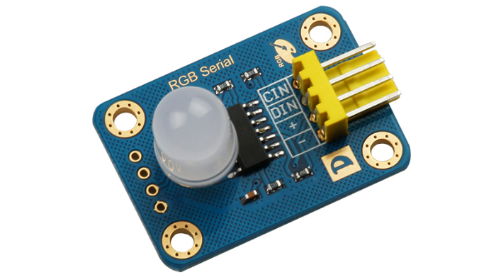
RGB 串行发光模块是基于 P9813 全彩 LED 驱动芯片的 RGB 模块,LED 选用了雾状的 RGB,防止通电时它发出非常刺眼的光。模块使用两线串行通信方式,最大限度的节省单片机的接口,单个模块的工作电流只有大约 20mA,支持多个模块通过前级模块输出接口与后级模块输入口连接的方式进行级联,最多可同时级联 1024 个同类模块,与 Arduino、Raspberry Pi 等主流硬件都可以配合使用,多个 RGB 模块级联在一起我们可以制作很多炫彩的装饰品,重要的是不管多少个模块级联在一起,都只是占用了单片机的两个数字接口!
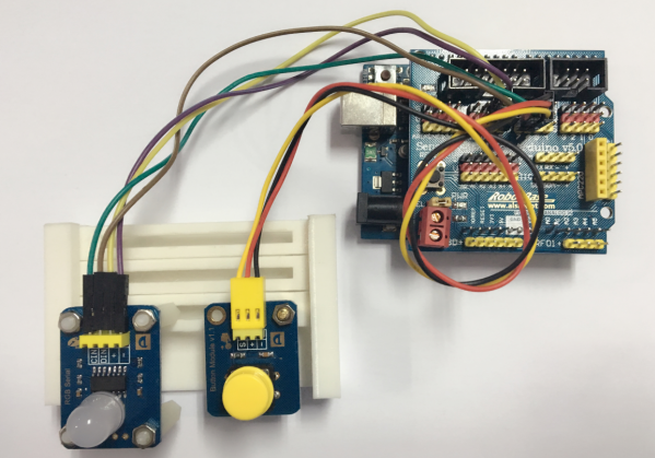
下面我们就使用RGB Serial 模块来制作一个简易台灯,它可以通过一个小按键来控制RGB不同的状态
在实验前,先对RGB Serial模块的接口做个简单的介绍
在之前的介绍中也提过,模块使用的是两线串行通信方式,它的四个输入引脚分别是:+、-、CIN、DIN
l -:电源地
l +:电源正极
l CIN:串行输入时钟线
l DIN:串行输入数据线
RGB Serial模块同样提供了四个输出引脚,用于模块之间的级联,分别是:+、-、COUT、DOUT
l -:电源地
l +:电源正极
l COUT:串行输出时钟线
l DOUT:串行输出数据线
接口如下图所示:

* 试验代码
#include <ChainableLED.h>
#define button 6
#define ledCount 1
int val = 0;
int old_val = 0;
int state = 0;
float j,f,k;
ChainableLED leds(7, 8, ledCount);
void setup()
{
Serial.begin(9600);
leds.init();
pinMode(button,INPUT);
}
float hue = 0.0;
boolean up = true;
void loop()
{
if(debounce(button) == 1)
{
color1();
}
else if(debounce(button) == 2)
{
color2();
}
else if(debounce(button) == 3)
{
color3();
}
else if(debounce(button) == 4)
{
color4();
}
else if(debounce(button) == 5)
{
color5();
}
else
leds.setColorRGB(0, 0, 0, 0);
}
int debounce(int pin)
{
val = digitalRead(button);
if((val == LOW) && (old_val==HIGH))
{
state++;
delay(40);
if(state >= 6)
state = 0;
}
old_val = val;
return state;
}
//随机变化
void color1()
{
for (uint8_t t = 0; t < ledCount; t++)
{
uint8_t red = 52*(1+sin(t/2.0 + j/4.0 ));
uint8_t green = 52*(1+sin(t/1.0 + f/9.0 + 2.1));
uint8_t blue = 52*(1+sin(t/3.0 + k/14.0 + 4.2));
leds.setColorRGB(t, red,green,blue);
}
j+=random(1,20)/6.0;
f+=random(1,20)/6.0;
k+=random(1,20)/6.0;
}
//三色闪烁
void color2()
{
leds.setColorRGB(0, 0,0,0);
for (uint8_t t = 0; t < ledCount; t++)
{
uint8_t red = 52*(1+sin(j/4.0 ));
uint8_t green = 52*(1+sin( f/9.0 + 2.1));
uint8_t blue = 52*(1+sin(k/14.0 + 4.2));
leds.setColorRGB(t, red,green,blue);
}
j+=random(1,20)/6.0;
f+=random(1,20)/6.0;
k+=random(1,20)/6.0;
}
//蓝色呼吸
int bri = 0, st = 0;
void color3()
{
if(bri>=100) st=1;
if(bri<=5) st=0;
if(st==1)bri=bri-5;
else bri=bri+5;
for(int t=0;t
{
leds.setColorRGB(t, 0, 0, bri); // parameter description: led number, red, green, blue, flash mode
}
delay(20);
}
// 绿色呼吸
void color4()
{
if(bri>=100) st=1;
if(bri<=5) st=0;
if(st==1)bri=bri-5;
else bri=bri+5;
for(int t=0;t
{
leds.setColorRGB(t, 0, bri, 0); // parameter description: led number, red, green, blue, flash mode
}
delay(20);
}
//红色呼吸
void color5()
{
if(bri>=100) st=1;
if(bri<=5) st=0;
if(st==1)bri=bri-5;
else bri=bri+5;
for(int t=0;t
{
leds.setColorRGB(t,bri, 0, 0); // parameter description: led number, red, green, blue, flash mode
}
delay(20);
j+=random(1,28);
}
* 试验效果
当按下大按钮模块的按键时,RGB Serial根据预设状态依次变化:
按下第一次,RGB Serial 颜色随机变化;
按下第二次,RGB Serial模块三色闪烁;
按下第三次,RGB Serial模块为蓝色呼吸灯状态;
按下第四次,RGB Serial模块为绿色呼吸灯状态;
按下第五次,RGB Serial模块为红色呼吸灯状态;
按下第六次,RGB Serial模块熄灭;以此循环
这里只是给大家做了一个小实验,在实际制作过程中,我们可以给RGB Serial模块加上透明的外壳,让闪烁看起来更加美观,要了解更多内容,大家可以点击进入:Supermaker团队为我们精心拍摄的视频: http://supermaker.tv/video/245.html
----------------------------------------------------------------------------------------------------------------
奥松机器人官网:www.robotbase.cn
微信号:搜索公众号“奥松机器人”
QQ群: 271230889(讨论,解惑)
微博:@奥松机器人基地
----------------------------------------------------------------------------------------------------------------
温馨提示:予人玫瑰,手留余香;如果你喜欢这篇文章,不妨转发推荐给你身边的朋友!
近期新闻
热门新闻

奥松智能微信